
Post 3: PS–PL Integration (Vitis Setup + Testing)
Published:
Written by Shreya Datir, in collaboration with Muhammad Farhan Azmine
PART 3: PS–PL Integration (Vitis Setup + Testing)
In Part 2, we walked through setting up the Zynq Processing System in Vivado, enabling UART0 (EMIO) and UART1 (MIO), connecting our custom UART RTL in the PL, and generating the bitstream. We wrapped up by exporting the hardware to an .xsa file which will bridge our Vivado design into Vitis.
Now, in this post, we’ll use that .xsa file to set up a platform in Vitis, configure the BSP, and build a bare-metal application that tests our UART design directly on the board.
BSP & Bare-Metal Project Setup (Vitis)
The first step is to create a Vitis platform project using the exported hardware file. Vitis will automatically generate a Board Support Package (BSP), which includes the drivers and libraries for the PS peripherals.
One important BSP setting is STDIN/STDOUT, which tells Vitis which UART to use for console I/O functions like xil_printf().
- We map STDOUT to PS-UART1 (MIO) so that debug prints appear on the PC terminal.
- At the same time, PS-UART0 (EMIO) is connected internally to our RTL UART in the PL for loopback testing.
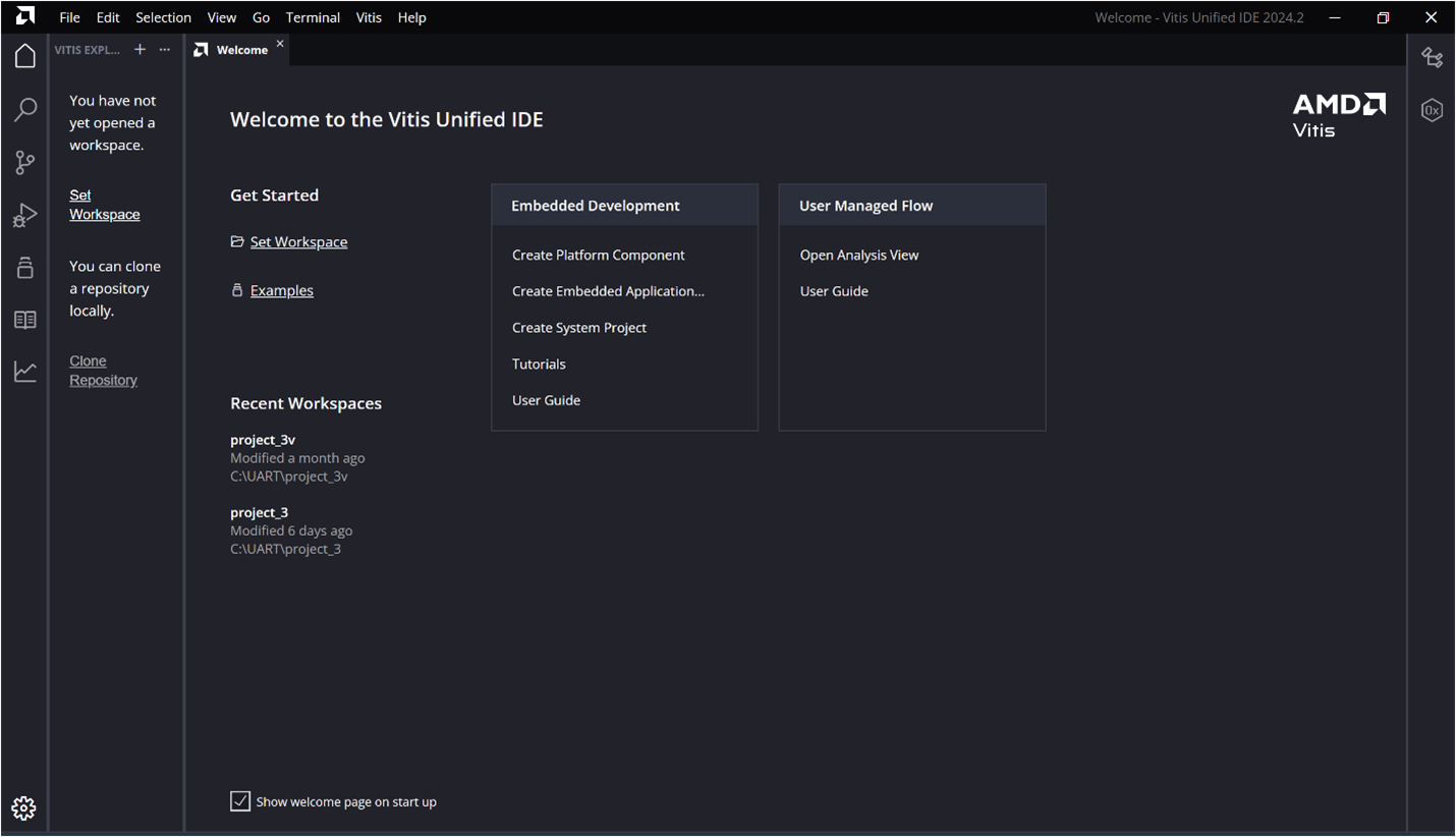
Step 1: Launch the Vitis Unified IDE and select (or create) a workspace directory where your project files will be stored.
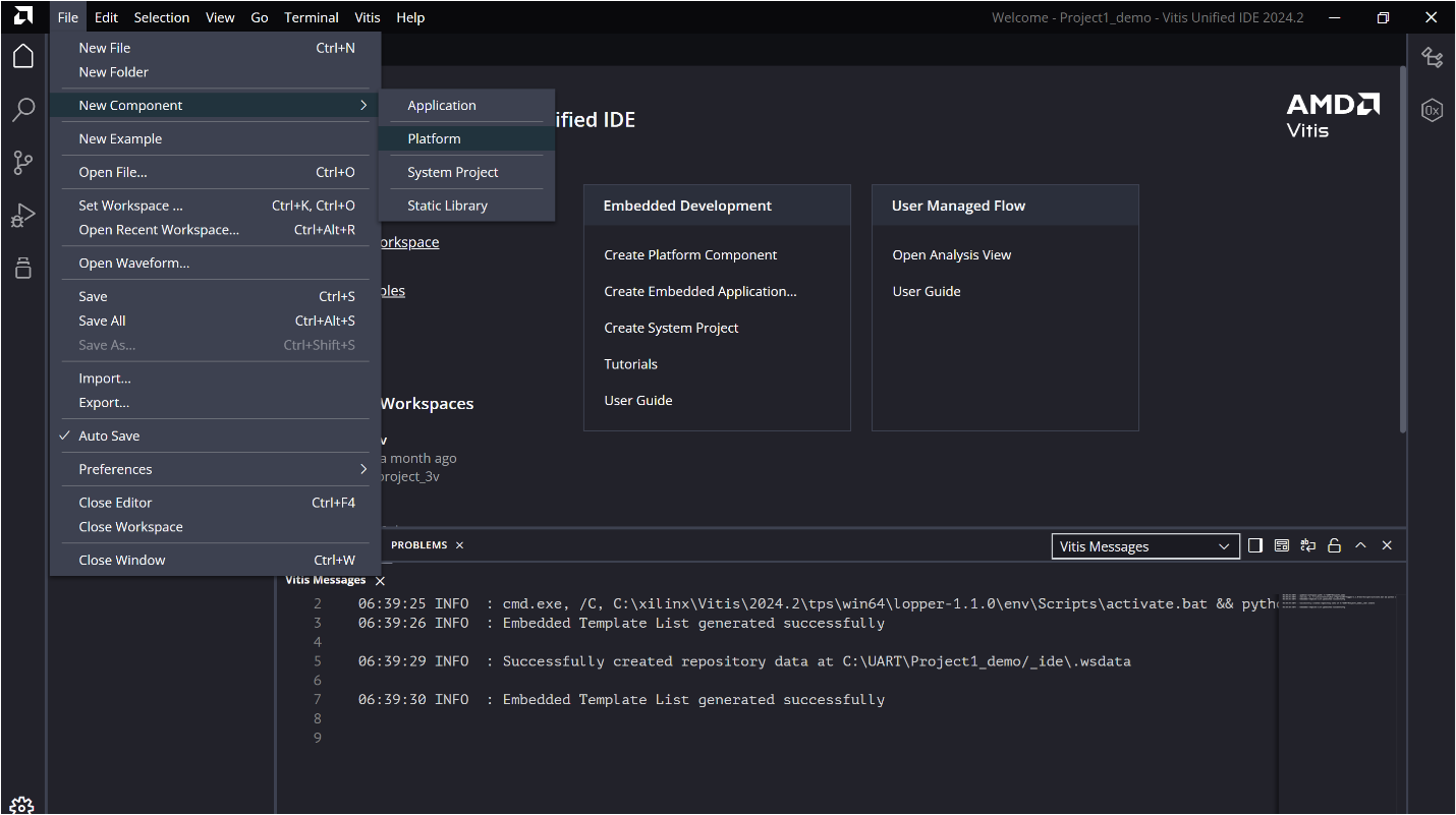
Step 2: From the menu bar, go to File → New Component and create a new Platform Component.
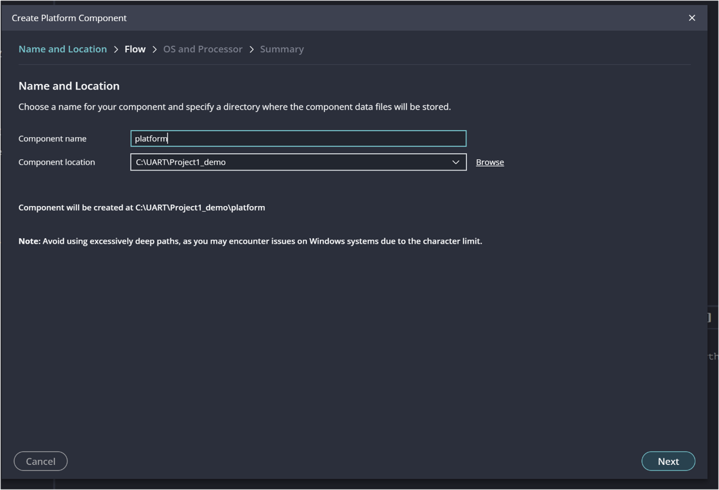
Choose a name and specify a location
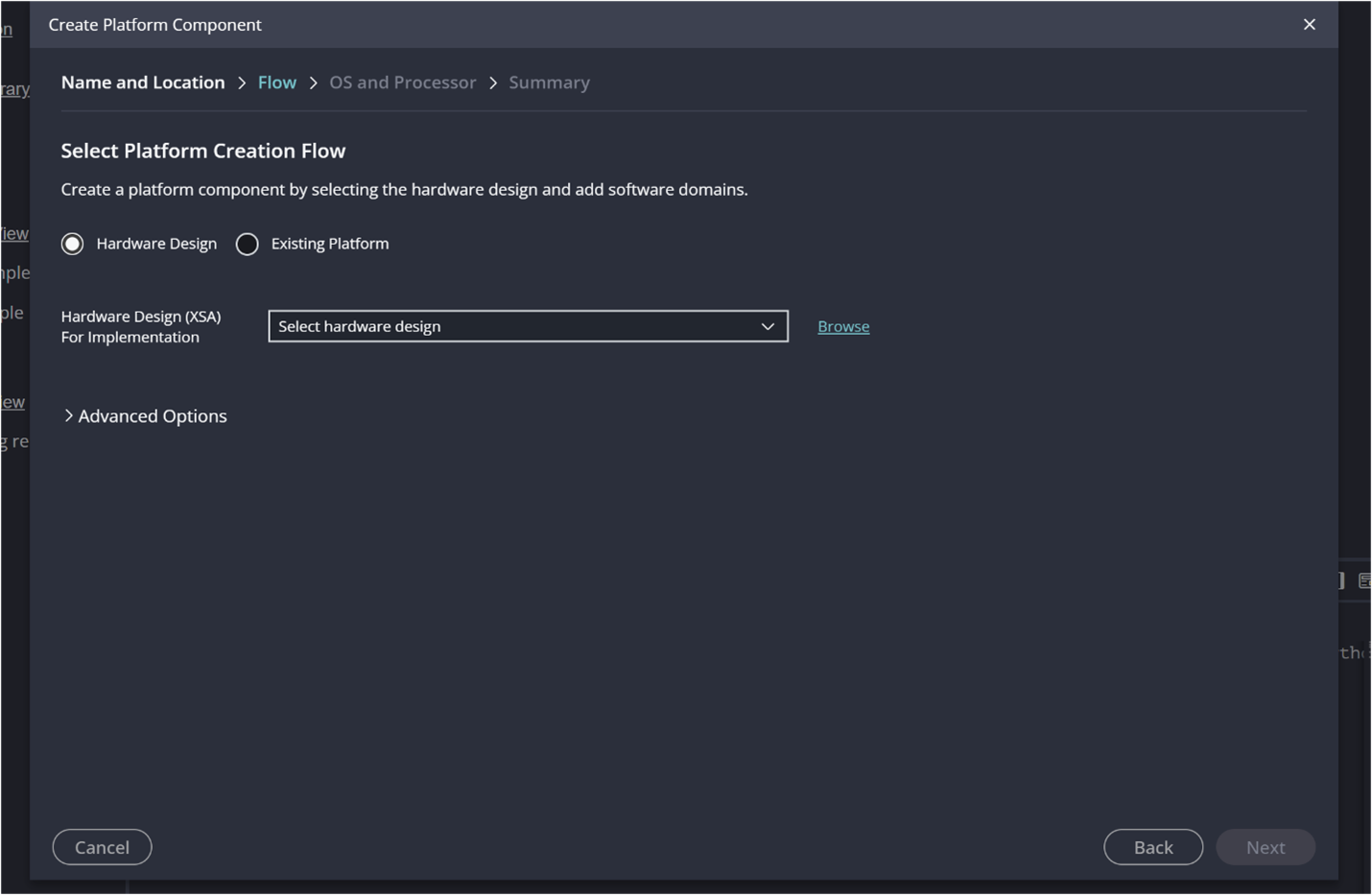
On the Select Platform Creation Flow page, choose Hardware Design. Click Browse to locate your exported .xsa file and then click OK.
Once the XSA file is loaded, Vitis automatically generates the System Device Tree (SDT). The SDT metadata is then used to populate the available processor list. From this list, select standalone as the operating system and choose the processor ps7_cortexa9_0.
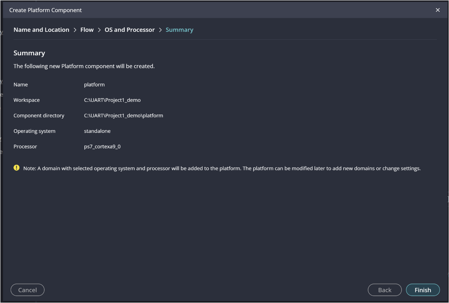
Leave the Generate Boot Artifacts option enabled, as shown in the figure below and click Next.

Review and click Finish.
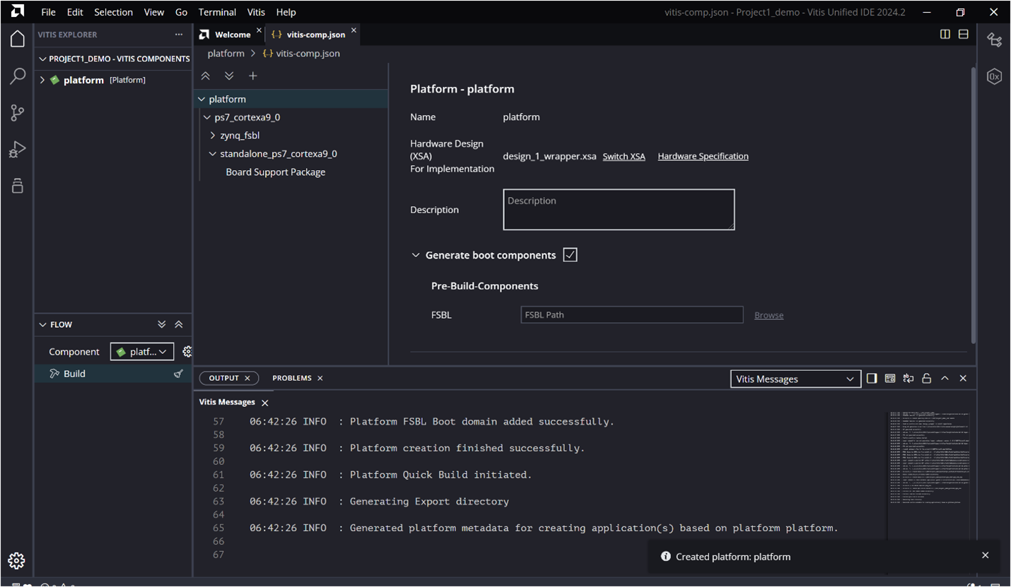
Step 3: Once the platform project is created, go to the Vitis Components view. Double-click on the platform to open it and display the Platform View, as shown in the figure below.
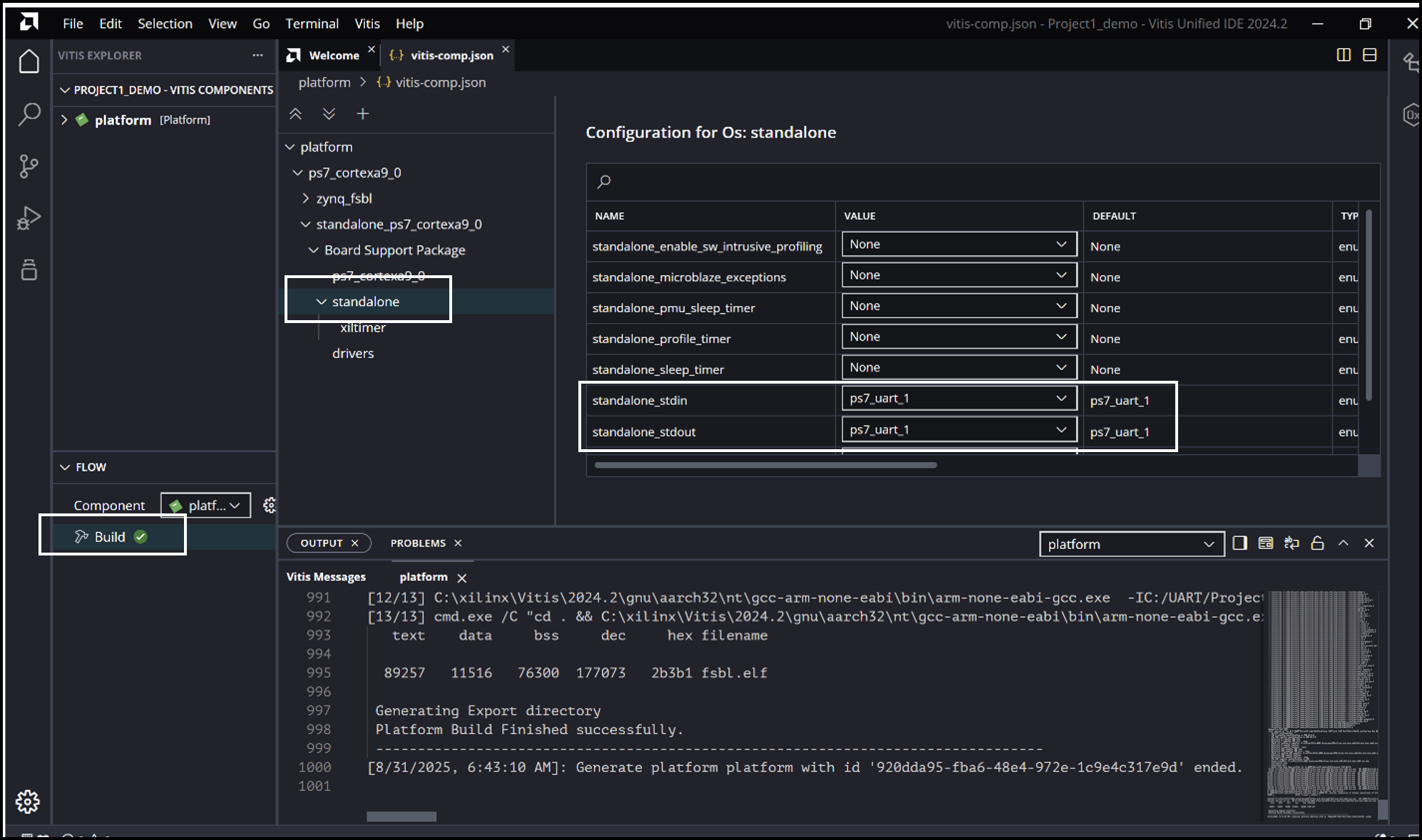
Step 4: In the Vitis Components view, expand platform → Settings → vitis-comp.json. Within vitis-comp.json, expand the hierarchy under OS: standalone and check the configuration for standalone_stdin and standalone_stdout. Make sure they are mapped to the UART configured as MIO in the design (UART1 in this case).
Next, Build the platform.
As the project builds, we can see the output in the Console window.
Step 5: Creating an Application Component.
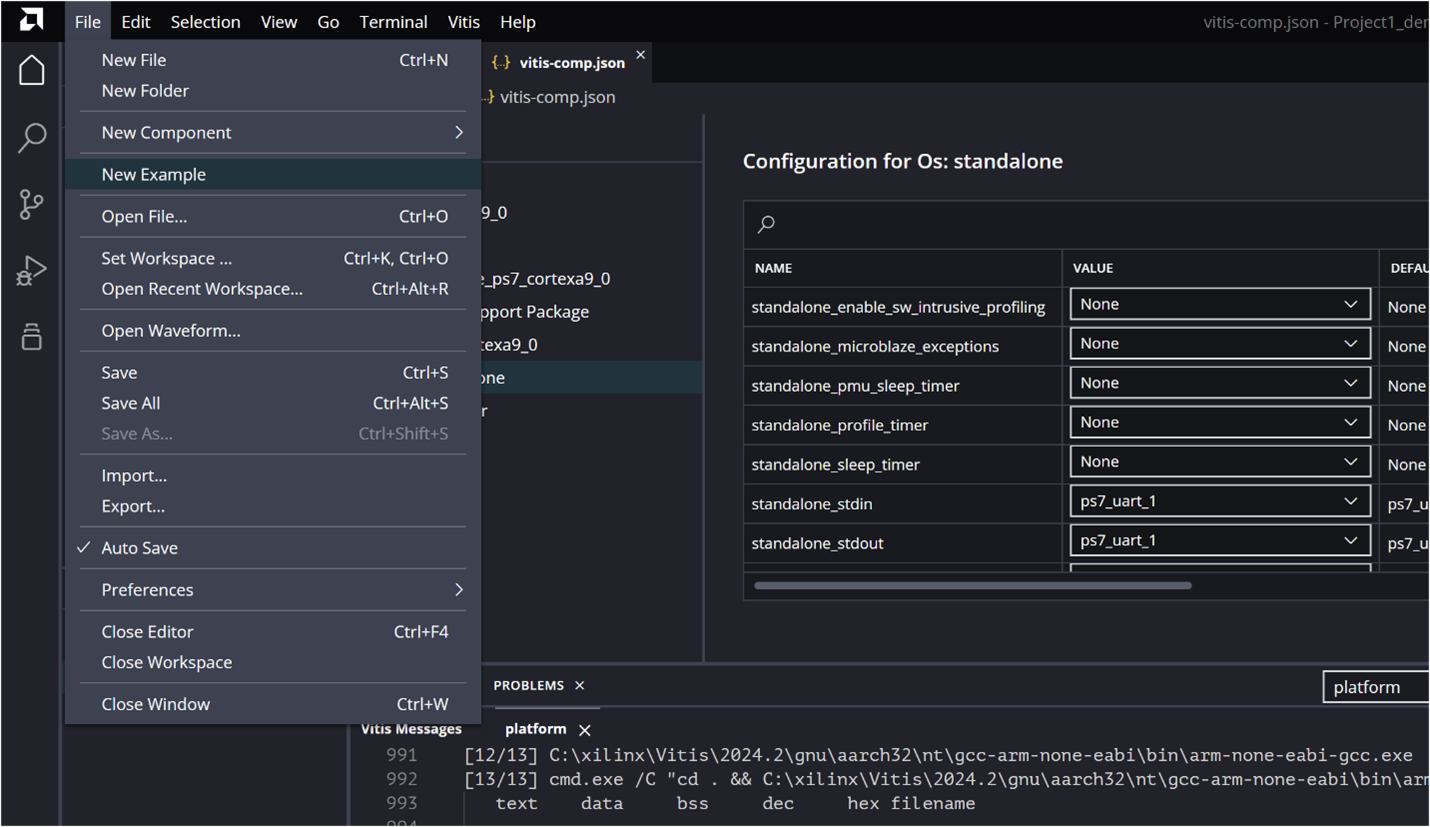
There are two ways to create an Application template in the Vitis Unified IDE. You can either use the Examples icon in the activity bar on the left side of the IDE, or go to File → New Component → Application. The second method creates an Empty Application template. [Reference]
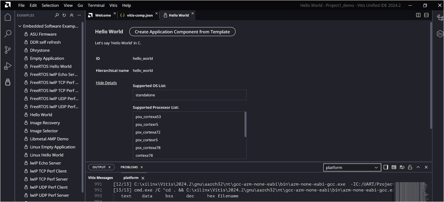
Here, we’ll create the application using an Example: go to File → New Example.
Select a suitable template and click Create Application Component from Template. For this tutorial, we’ll use the Hello World template.
In the Create Application Component wizard, click Next and choose the platform created in the previous step.
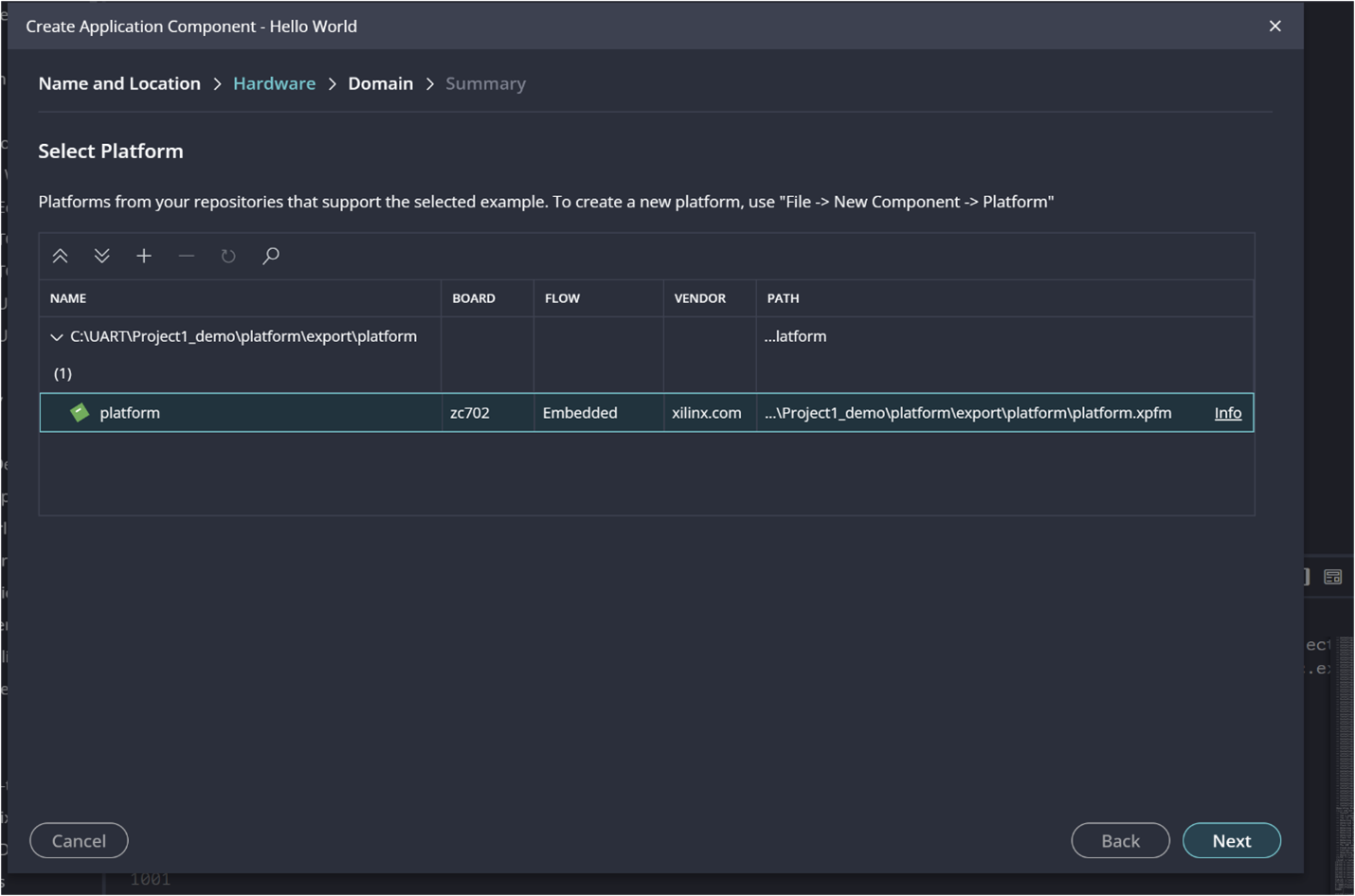
This will use the domain generated in the platform by default. Click Next and Finish. The application project will be created, as shown below.
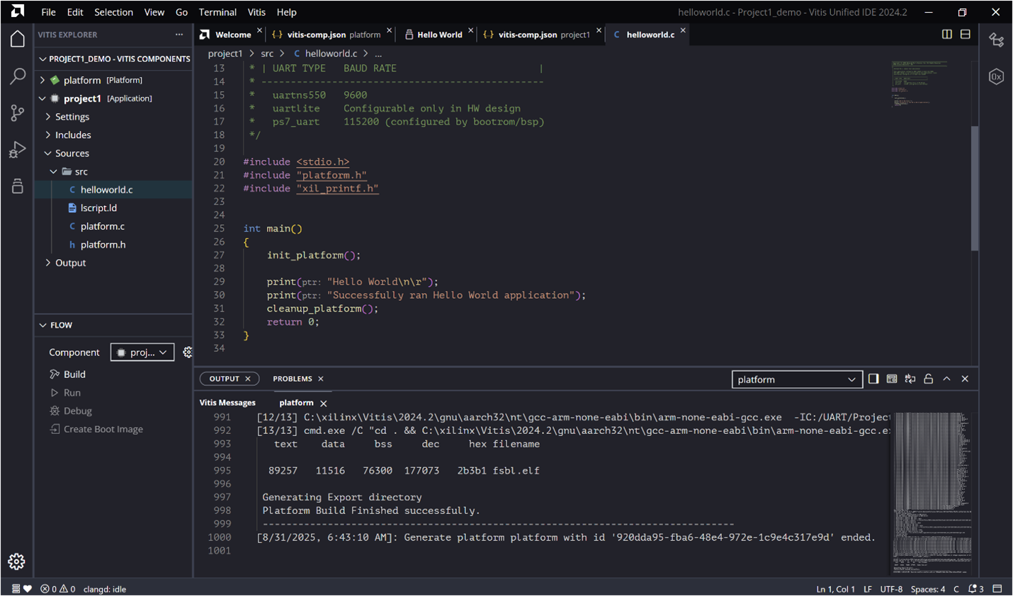
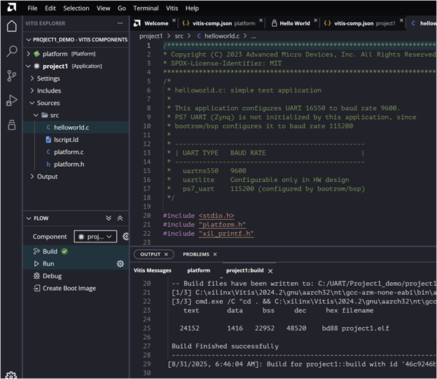
In the Vitis Explorer pane on the left, under Sources, you can view and edit the source code. Here, we added the UART code (explained later). Once the code is ready, build the application.
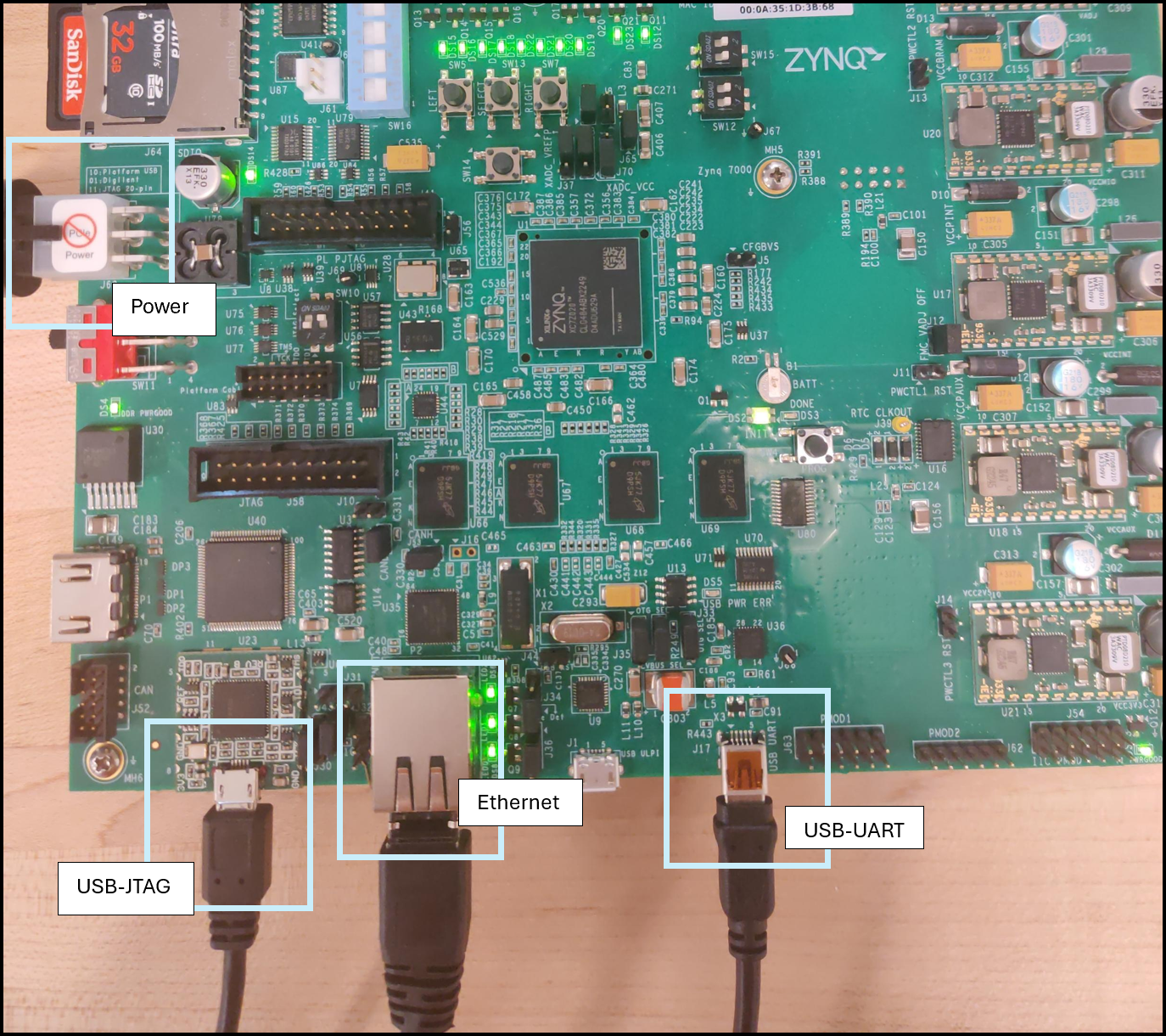
Step 6: Setting up the board connection.
- Connect the power cable to the board.
- Connect the USB UART cable to J17.
- Connect the USB JTAG cable.
Once your board is connected and powered, your computer should detect the USB-UART adapter automatically. If it doesn’t, you’ll need to install the correct driver. For most adapters based on the Silicon Labs CP210x bridge, you can find the official Virtual COM Port (VCP) drivers on Silicon Labs’ site:
Access the driver download page here: Silicon Labs CP210x USB-to-UART Bridge VCP Drivers.
This page provides downloads for Windows, macOS, Linux, and Android. After downloading, install the driver (e.g. CP210xVCPInstaller_x64.exe on Windows). Once installed, your operating system should expose a COM port (e.g., COM3 on Windows or /dev/ttyUSB0 on Linux), which your terminal program can then use.
Step 7: Open the serial monitor
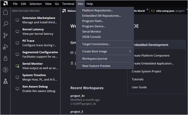
You can use the built-in serial monitor in Vitis or an external tool like PuTTY. To open it in Vitis, go to the menu bar → Serial Monitor. If the option isn’t visible, enable it by turning on New Feature Preview in the settings, then activate the serial monitor feature from there.
Once, the serial monitor is enabled, open it and choose the appropriate baud rate at the corrcet port. 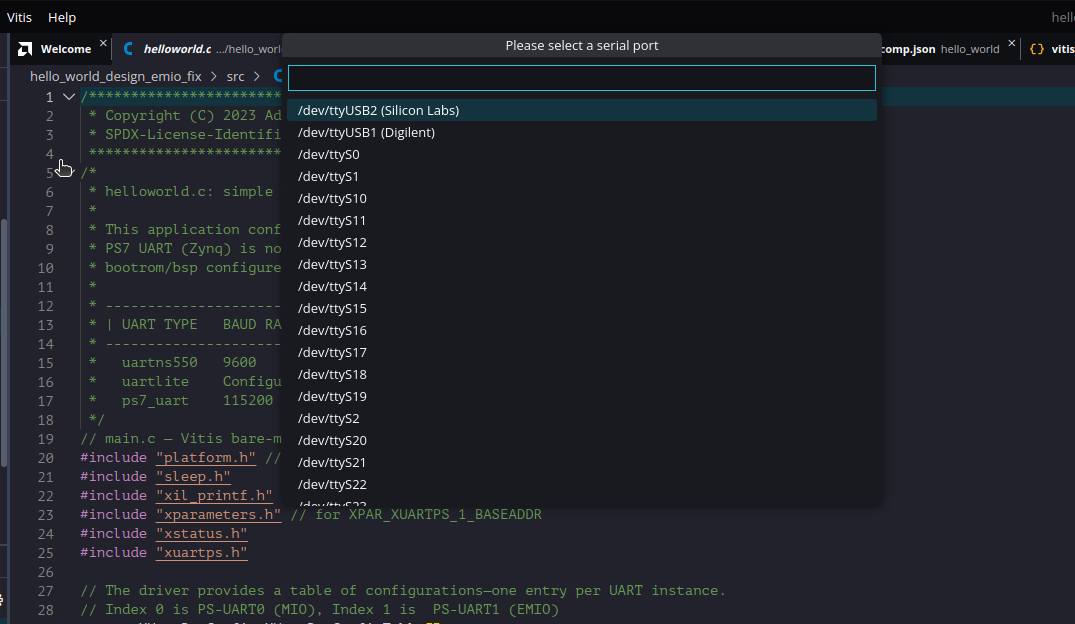
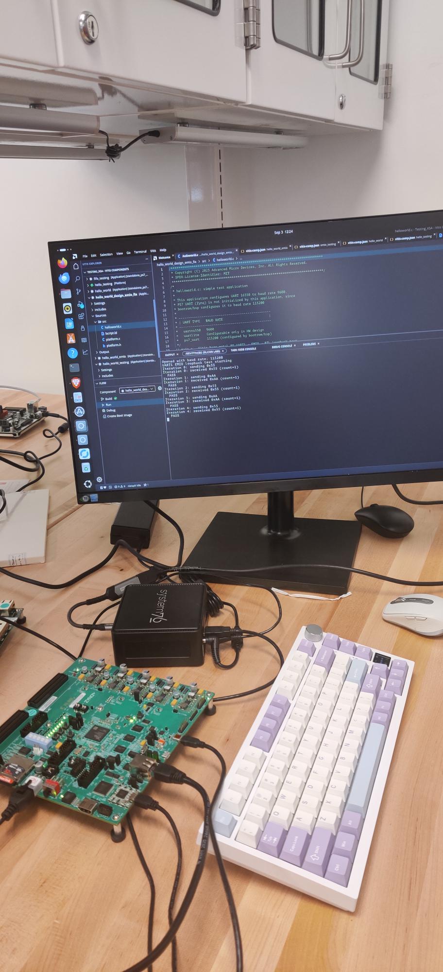
Step 8: Run the code and check the output in the serial monitor
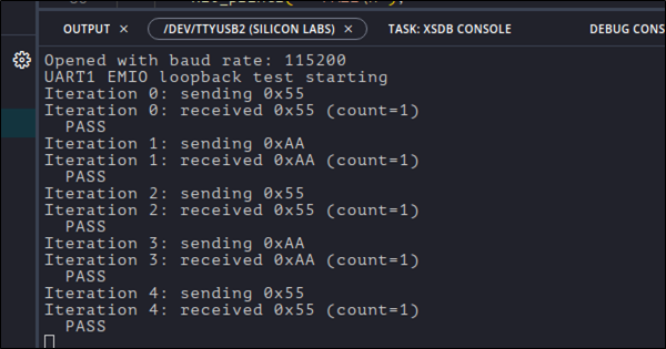
Verify the loopback test messages, where each byte sent (e.g., 0x55, 0xAA) is echoed back by the UART RTL through EMIO. The console will display both the transmitted and received values along with a PASS message for each iteration, confirming correct operation.
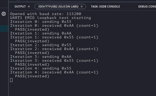
To further verify the integration, we also tested the design with the inverter logic in the PL. As shown in the console output below, each transmitted byte (0x55, 0xAA) is received back in its inverted form (~0x55 = 0xAA, ~0xAA = 0x55). The log confirms correct operation with the PASS (inverted) messages.
PS-UART Driver API
To talk to the RTL UART in C code, we use the Xilinx UART driver. The main functions are:
XUartPs_CfgInitialize() – It takes in the hardware configuration (from the .xsa export) and prepares the driver for use. This step ensures the PS UART0 is properly linked to the correct base address in memory.
XUartPs_SetBaudRate() – sets the PS UART baud rate. The baud must match the UART logic in the PL so both ends agree on bit timing.
XUartPs_SendByte() – sends a byte out of the PS UART0. This function writes the byte into the TX register of the PS UART peripheral. In our setup, this byte is routed through EMIO into the PL.
XUartPs_RecvByte() – reads a byte from the PS UART0. This function checks the RX register of the PS UART peripheral. In our setup, the data here is coming back from the PL after passing through the receiver FSM, inverter, and transmitter FSM.
These functions make it easy to control the UART directly from our bare-metal application. All xil_printf() statements in the code print through PS-UART1 (MIO), which shows up on the PC’s serial terminal. At the same time, PS-UART0 (EMIO) is driving data into the UART RTL inside the PL.
Building the Loopback Test Application
Our bare-metal loopback program follows a straightforward structure:
- init_platform() – initialize hardware resources.
- UART driver initialization.
- Main loop:
- Send a byte from the PS UART into the PL.
- Receive the processed (inverted) byte back from the PL.
- Print both values to the console.
This design mirrors the simulation testbench from Part 1, but instead of being written in SystemVerilog, the testbench logic is now running as C code on the PS CPU.